 Click on any photo larger image
3 TON MOBILE YARD CRANE
This was Coles first true none rail mobile crane. Made however using their existing technology, it was essentially their steam crane on wheels but powered by a large diesel engine.
|
|
|
This was not the first free mobile set free from the rail tracks however, a very simlar unit only with a steam boiler was pictured here in 1920 at Stothert & Pittin works Newark.
Left >
Coles would have felt that they must move into the none rail mobile market as Ransomes & Rapier had brought out a three wheel loading crane in 1923 and it was proving popular.
< Right
|
|
|
|
|
Diesel 3 ton Yard Crane
1928
Finished model built 1:12 scale
27"x9"x15" high.
(675x225x375mm)
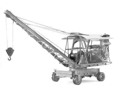
Here we have a 3 ton lift yard crane being built at Derby from about 1928 and with this unit we have a direct descendent of the steam crane. This machine has the same configuration as the steam unit only now the power comes from a large diesel engine.
|
|
|
The whole crane has now been freed from the limitations of the railway track and mounted upon it own independent carriage unit.
This carriage unit, like the train, is a substantial heavy base with solid tires on steel wheels with no suspension. This gives the necessary stability.
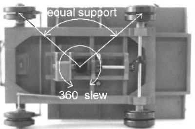
The wheels are placed at the limits of the four corners of the carriage equidistant from the rotating slew mounting, this arrangement gives the unit the same lift capacity all the way around.
|
|
|
 |
|
This means that it will not fall over when moving a load around from one side to the other.
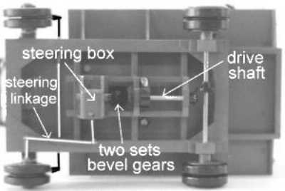
The drive to the crane jib, the winding drum and to the wheels of the carriage are all taken as direct drive from the engine.
This arrangement is further complicated by the new need for steering of the front wheels.
|
|
The steering and drive are achieved by having a double shaft passing through the pivotal point of the crane. The outer shaft driving the wheels and the inner shaft working the steering.
To reduce complication the steering wheel was placed directly over the canter point of the platform directly onto the steering shaft, the necessary reduction gearing being inside the steering box under the platform.
This double drive shaft is the direct precursor of the modern hydraulic mounting ring. (see technical details)
The crane arrangement is such that the weight of the engine counterbalances the jib and lift weight. Any differences in jib size and weight being taken allowed for in counterweights bolted to the back of the platform.
|
|
|
|
|
|
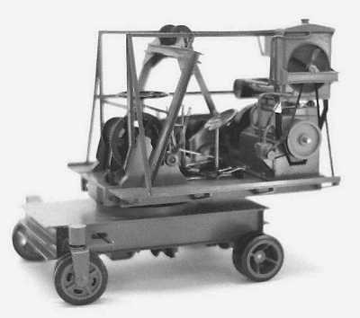
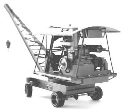
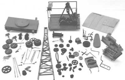
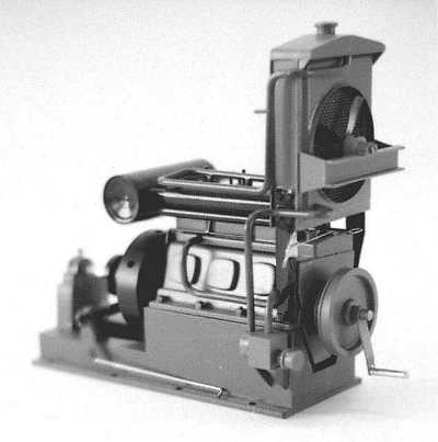
| The first picture above show the machine just before final assembly. All the components including all the gears and corrugated sheet roof all had to be hand made. The detail left shows the engine in its final mounted position.
It can be seen here how better engines and gear cutting methods would soon lead to the lighter and more mobile units to come.
|
)
)
)
)
)
)
)
)
)